 English
 Tiếng Việt
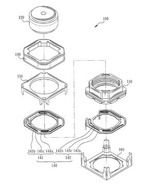
(en)An anti-shake lens driving apparatus is provided, including a lens carrier, for carrying at least a lens set; a magnet module, disposed on the outer surroundings of the lens carrier for pushing the lens carrier; a suspension part, further including an upper suspension resilient element and a lower suspension resilient element, the upper and lower suspension resilient elements respectively including a fixed part, a movable part and at least a suspension element; the at least a suspension element connecting the fixed part and the movable part; the fixed part being fixed to an upper cover and a base; the movable part being fixed to the upper and lower part of the lens carrier respectively; and the upper cover and the base being disposed respectively at the upper and lower part of the magnet module and the suspension part for providing protection.
You are contracting for Anti-shock lens driving apparatus
Expert Anti-shock lens driving apparatus


You are commenting for Anti-shock lens driving apparatus